TR / EN
Logo
TUNÇMAKSAN
Herringbone Gear
PRODUCT INFO

Herringbone Gear

Herringbone gears consist of two helical gear sections with opposite helix angles joined back-to-back. This construction cancels the axial thrust that helical gears would otherwise generate.
CAPACITY
Ø 10 — 3100 mm
MODULE/STANDARD
Mn 0.5 — 25.4
TYPE
DIN / ISO / SAE
EVALUATION

Herringbone Gear advantages and important considerations

Advantages

  • Cancels the axial forces — the main drawback of helical gears — by balancing them. No axial load is transmitted to shafts or bearings, no thrust bearing required.
  • Transmits higher torque than a spur gear of the same size.
  • Multiple teeth in contact simultaneously transmit power smoothly.
  • Can operate quietly at higher speeds.

Important Considerations

  • A more difficult and expensive manufacturing process than helical gears. Cutting the teeth correctly and aligning them back-to-back requires precise operations.
  • Requires more weight and volume than straight or helical gears.
  • Requires care during maintenance and repair. The channels between teeth must be cleaned and lubricated.
MANUFACTURING PROCESS

Herringbone Gear how is it manufactured?

01 / METHOD

Gear Profile Design

Module, pressure angle, number of teeth, tip diameter, root diameter, tooth depth, helix angle and profile shift coefficient are calculated.

02 / METHOD

Gear Blank Cutting

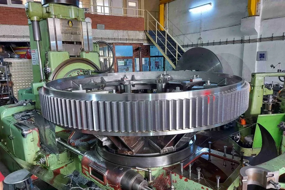
Turning, milling or forging produces the blank to the desired shape and size.

03 / METHOD

Tooth Generation

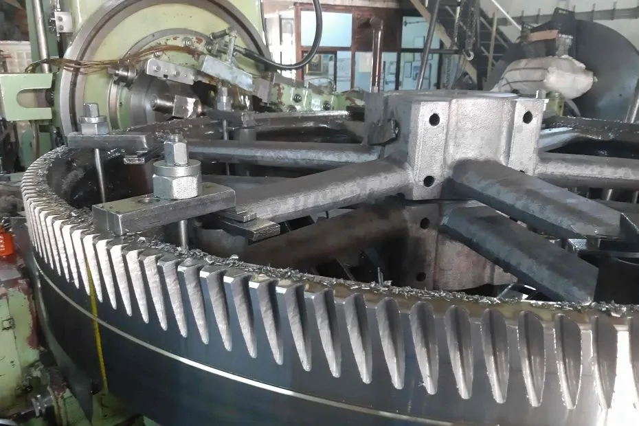
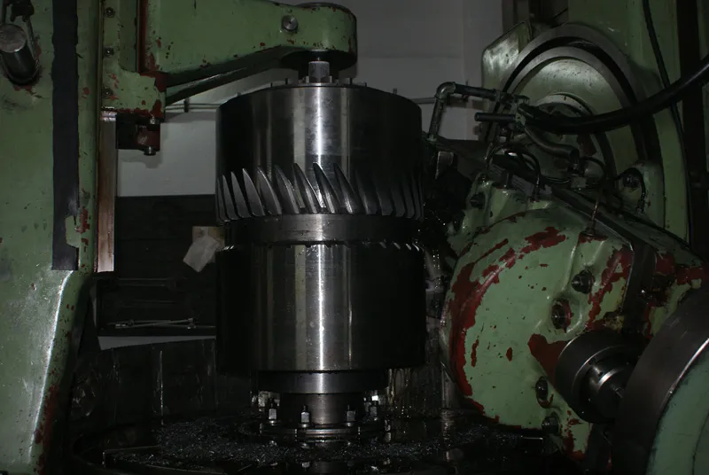
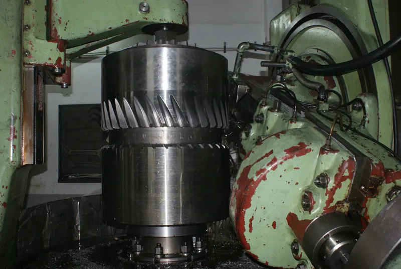
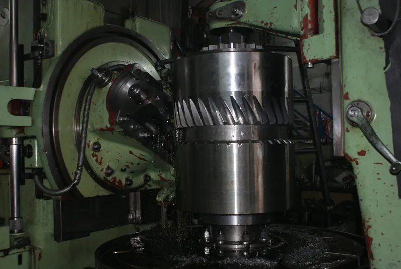
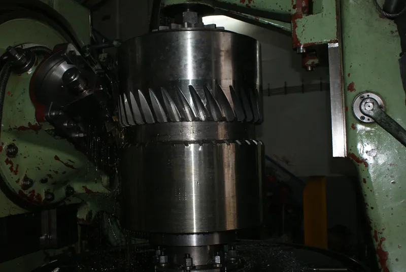
Teeth are generated by hobbing, milling or skiving.

04 / METHOD

Finishing

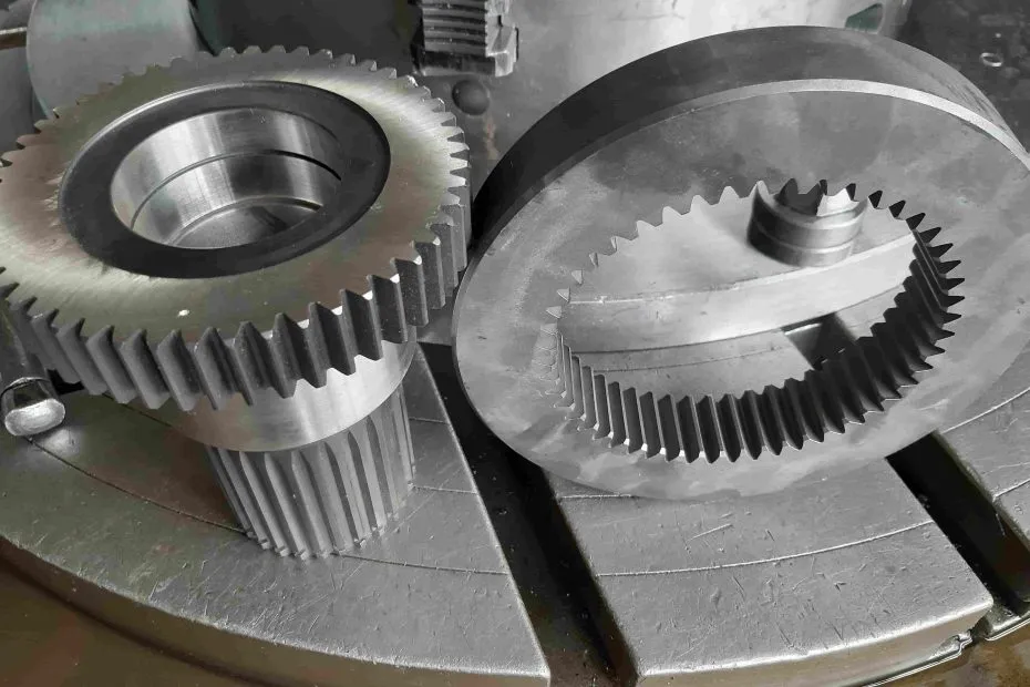
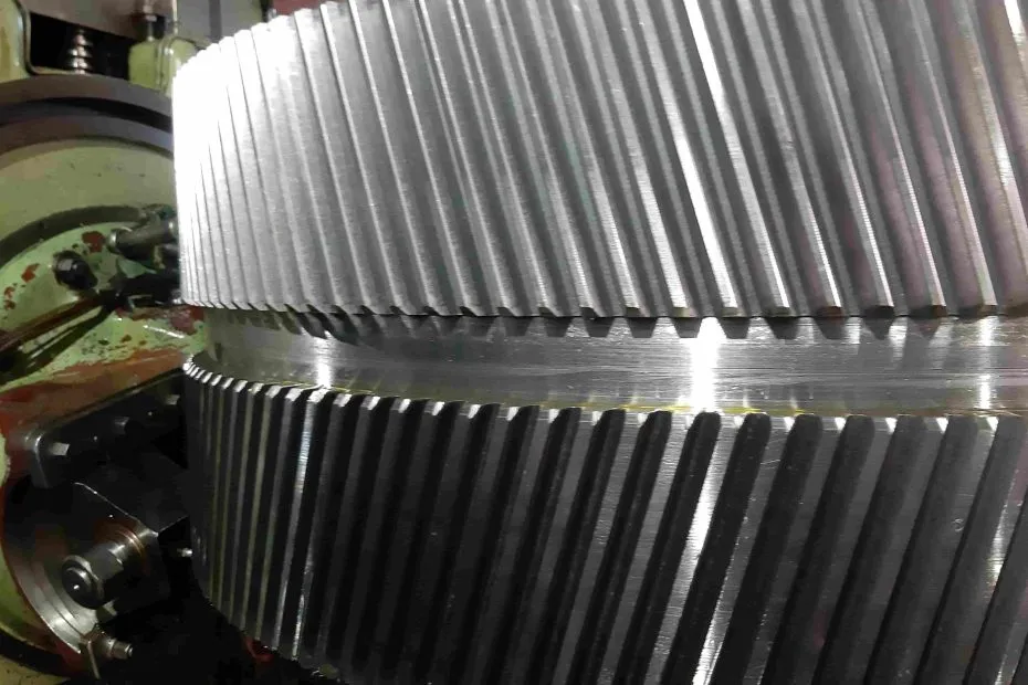
Grinding, honing, lapping or shaving improves accuracy and surface quality.

05 / METHOD

Hardening

Carburizing, nitriding, induction hardening or case hardening increases durability.

06 / METHOD

Inspection & Testing

Dimensional, profile, pitch, runout measurements and hardness tests verify the specification.

TECHNICAL INFO

Herringbone Gear calculation formulas

Symbol Name Formula Definition
mn Normal Module mn = d / z A measure of tooth size
d Reference Diameter d = mn × z The circle passing through the contact points
db Base Diameter db = d × cos(α) The circle from which the involute tooth profile begins
α Pressure Angle 14,5° / 20° Affects the transmitted force
da Tip Diameter da = d + 2mn The circle passing through the tooth tips
df Root Diameter df = d − 2,5mn The circle passing through the tooth roots
ha Addendum ha = 1,00 × mn Distance between reference and tip circles
hf Dedendum hf = 1,25 × mn Distance between reference and root circles
h Total Tooth Depth h = 2,25mn Distance between tip and root circles
β Helix Angle arctan(ts / πd) Affects the magnitude of axial thrust
AREAS OF USE

Herringbone Gear in which sectors is it used?

Herringbone gears are ideal for heavy-load, high-torque applications such as steel mills, marine drives, and reduction gear boxes — without requiring thrust bearings.
Steam Turbines
Large Machine Tools
Rolling Mill Equipment
Reduction Gears
Lifting Equipment
Industrial Shears
Transmissions
Marine Propulsion Propellers
Mining Equipment
Construction Equipment
Metalworking Equipment
GALLERY

Production samples

RELATED PRODUCTS

Other gear types we manufacture

Herringbone Gear request a manufacturing quote today.

Contact us via sample or technical drawing, we will provide a custom solution for your needs.

Quick Quote